A step stencil having two thicknesses1. STENCIL AND MISPRINTED BOARD CLEANING HANDBOOK.
Smd Stencils Design Aid Multi Circuit Boards
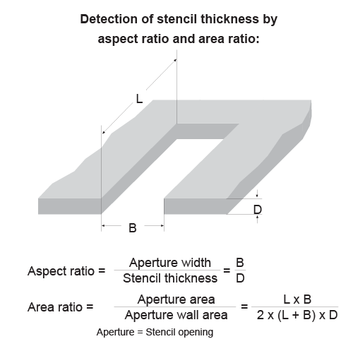
Width of bridge between apertures.
. Contribution is from screen-printing process where stencil design plays major role if considered other screen-printing parameters are optimized on which this paper is focused on. Find them all on the ANSI Webstore. The relationship of SMT component PCB lay-out and PCBA process are discussed in two steps.
It is intended as a guideline only. Device apertures are in areas where the stencil is thin and the large device apertures are in an area where the stencil is thicker. IPC-7525A - Stencil Design Guidelines 352 Step-Up Stencil This type stencil is useful when it is desirable to print thicker solder paste in a small portion of the stencil.
TERMS AND DEFINITIONS FOR INTERCONNECTING AND PACKAGING ELECTRONIC CIRCUITS. Stencil design for various surface-mount technology as well as mixed technology with through-hole or. This product replaced byIPC 7525B - Stencil Design Guidelines This product replacesIPC 7525 - Stencil Design Guidelines Browse Product Family.
The IPC stencil guidelines are the most commonly used and are a good starting point however they do not take into account outside variables that regularly come up in all manufacturing lines such as environmental conditions oven profile printing variables squeegee pressure under-board support squeegee speed etc. The step-upstep-down stencil is a special development for the adjustment of solder paste quantity fulfilling the needs of placement and soldering. STENCIL DESIGN FOR BGA PACKAGES O.
3425AIPC-7525AStencil Design GuidelinesStencil Design Guidelines标准为无铅工艺提供相关建议作为通用的设标准为无铅工艺提供相关建议. Hard Copies and PDFs Available. Stencil manufacturing and design PBGA package - Square aperture with side length equal to the diameter of pads - Foil thickness considerations as below - CSP take care of particle diameter in paste CBGA package - overprinting - Min.
DESIGN AND ASSEMBLY PROCESS IMPLEMENTATION FOR BOTTOM TERMINATION COMPONENTS. During the initial Stage of Stencil design it is imperative to arrest these problems. 830 am - 6 pm EST.
13 Overview Cleaning of stencils and misprinted PCBs has taken an increasingly important role in surface mount technology. IPC 7525B IPC. 11 Terms and Definitions All terms and definitions used throughout this handbook are in compliance with IPC-T-50.
This includes differences for tin lead and lead free solder paste overprint two-print and step stencil designs. It is intended as a guideline only. It is intended as a guideline only.
The IPC-7525C standard provides guidance for the design and fabrication of stencils for solder paste and surface-mount adhesive with much of the content based on the experience of stencil designers fabricators and users. Design of Stencil should comply with IPC-7525A. Ad Search and Buy IPC Codes and Specifications.
Stencil Design Guidelines 1 PURPOSE This document provides a guide for the design and fabrication of stencils for solder paste and surface-mount adhesive. Stencil Design Guidelines 1 PURPOSE This document provides guides for the design and fabrica-tion of stencils for solder paste and surface-mount adhe-sive. Fine and ultra-fine pitch lands together with.
The handbook serves as a guide to users or prospec-tive users of stencilmisprint cleaning technology. STM STENCIL DESIGN AND CONSIDERATION BASE ON IPC Page 6 of 34 02062007 of circuit design into an organized manner that will give the same function as physical wiring. Standards Referencing This Book- Show below - Hide below IPC T 50.
Contribution is from screen-printing process where stencil design plays major role if considered other screen-printing parameters are optimized on which this paper is focused on. IPC 7525A-2007 Stencil Design Guidelines This document provides guidelines for the design and fabrication of stencils for solder paste and surface-mount adhesive. Ad Print from PDF Association Connecting Electronics Industries Standards.
IPC-7525A - February 2007 IPC-7525 - May 2000. Printing performance depends on many different variables and therefore no. IPC-7525A Stencil Design Guidelines Developed by the Stencil Design Task Group 5-21e of the Assembly and Joining Processes Committee 5-20 of IPC Users of this publication are encouraged to participate in the development of future revisions.
A sample order form and user inspection checklist are also included. Documents sold on the ANSI Webstore are in electronic Adobe Acrobat PDF format however some ISO and IEC standards are available from Amazon in hard copy format. The paper presents the innovative technology of step-up and step-down stencils in a laser cutting and laser welding process.
Much of the content is based on the experience of stencil designers fabricators and users. According to IPC design guidelines 7525B there should be 89mm 035 keep-out. Definitions denoted with an asterisk below are reprints from IPC.
An example would be a ceramic BGA where it is necessary t. 12 foil_thickness 2. This document provides guidance for the design and fabrication of stencils for solder paste and surface-mount adhesive.
Much of the content is based on the experience of stencil designers fabricators and users. A basic understanding of stencilmisprint cleaning pro-cesses. IPC75252000-Stencil Design Guidelines-Customer Service.
This standard establishes the guidelines for the design and fabrication of stencils for solder paste and surface mount adhesive with discussion on through-hole mixed technology and includes the differences for tin lead and lead-free solder paste overprint two-print and step stencil designs. Much of the content is based on the experience of stencil designers fabricators and users. Design of Stencil should comply with IPC-7525A.
Thinner stencil foil but print other devices using a thicker stencil foil. IPC 3000 Lakeside Drive Suite 309S Bannockburn Illinois 60015-1249 Tel 847 6157100 Fax. IPC-7525 Revision C November 2021 - Stencil Design Guidelines.
It is intended as a guideline only. During the initial Stage of Stencil design it is imperative to arrest these problems. This document provides guidance for the design and fabrication of stencils for solder paste and surface-mount adhesive.

Ipc 7525 A Stencil Design Guidelines Pdf Docer Com Ar

Ipc 7525 Stencil Design Guidelines

Ipc 7525c
Ipc 7525a 2007 Stencil Design Guidelines

Ipc 7525c

Ipc Document Revision Table Ipc International Inc
Ipc 7251 Generic Requirements For Through
Ipc 7525c
0 comments
Post a Comment